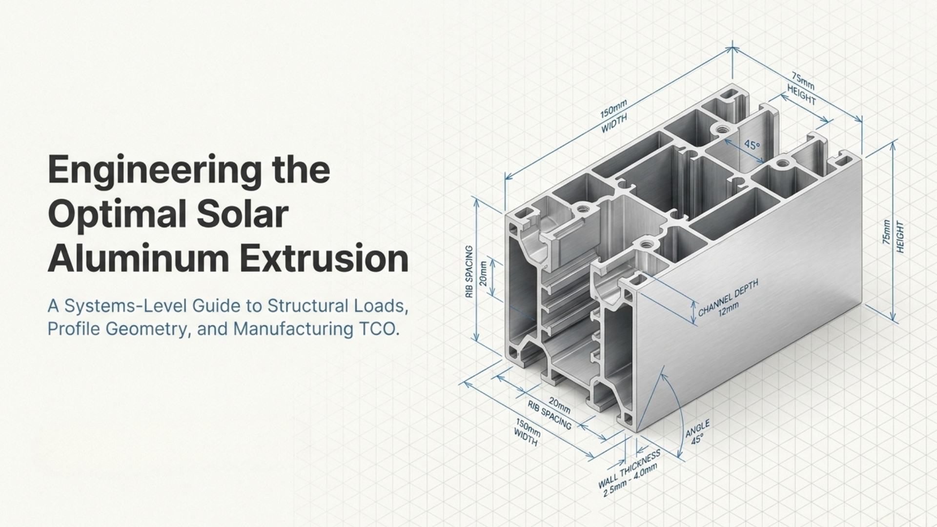
Designing an aluminum extrusion for solar mounting systems requires more than selecting an alloy and specifying a rectangular profile. Engineers must evaluate structural loads, span, section geometry, wall thickness, connection points, tolerances, fabrication, surface finish and production volume as one system.
For photovoltaic mounting applications, the right extrusion can reduce material usage, simplify assembly and improve dimensional consistency. However, reducing profile weight without evaluating stiffness, deflection and connection requirements can create downstream engineering problems.
This guide explains the main engineering decisions involved in developing an aluminum extrusion for rooftop PV, ground-mounted solar, solar carports and other photovoltaic mounting applications.


What Should Be Defined Before Designing a Solar Aluminum Extrusion?

The extrusion design should begin with the application rather than with an existing aluminum profile. Before creating the cross-section, the engineering team should define how the component will be loaded, connected, manufactured and installed.
A useful preliminary design specification should include:
- Solar application: rooftop, ground-mounted, carport, tracker or equipment support
- Unsupported span: distance between structural support points
- Loading: wind, snow, dead load and applicable project loads
- Connection method: clamps, bolts, brackets, fasteners or integrated channels
- Module dimensions: relevant panel size and mounting interface
- Alloy and temper: selected according to mechanical and manufacturing requirements
- Wall thickness: established according to strength, stiffness and extrusion feasibility
- Dimensional tolerances: based on functional interfaces
- Surface finish: mill finish, anodizing or powder coating
- Cut length: stock length and finished component length
- Secondary fabrication: cutting, drilling, punching, tapping or CNC machining
- Production volume: prototype quantity, initial order and annual demand
Defining these parameters early prevents a common engineering mistake: designing the extrusion first and attempting to make the application fit the resulting profile.
Engineering Principle: A solar extrusion should be designed around the load case, connection geometry and manufacturing process—not simply around a desired outside dimension or target weight.
Step 1: Define the Function of the Solar Extrusion

The first design question is what the aluminum profile must actually do.
A photovoltaic extrusion may function as a mounting rail, module frame, structural support, equipment bracket, cable-management component or part of a larger support assembly.
Each function creates different design priorities.
| Component | Primary Function | Important Design Consideration |
|---|---|---|
| Solar mounting rail | Supports and connects PV modules | Span, stiffness and connection geometry |
| Module frame | Supports the solar panel perimeter | Glass interface and dimensional accuracy |
| Ground-mount support | Transfers structural loads | Wind, snow, span and connection loads |
| Solar carport profile | Structural and architectural support | Strength, appearance and drainage integration |
| Equipment support | Supports electrical or mechanical equipment | Strength and machinability |
A mounting rail, for example, should not be designed using the same criteria as a visible module frame. The rail may prioritize stiffness and connection performance, while the frame may place greater emphasis on dimensional repeatability and surface appearance.
Step 2: Determine the Solar Mounting Load Case

Once the component function is established, the next step is to determine the loads acting on the profile.
Solar mounting components can experience several load types:
- Dead weight from photovoltaic modules and mounting components
- Wind pressure and wind uplift
- Snow loads
- Local connection loads
- Thermal expansion effects
- Loads transferred through clamps and fasteners
- Installation and maintenance loads where applicable
The actual design load depends on the project location, mounting configuration, structural system and applicable engineering requirements.
For this reason, a solar aluminum extrusion should not be specified solely by its nominal dimensions. A 40 × 40 mm profile, for example, can have very different performance characteristics depending on wall thickness, internal geometry, alloy and orientation.
Step 3: Establish the Required Span and Support Spacing

Span is one of the most important variables in solar extrusion design. A mounting rail carrying the same module load can require a substantially different cross-section when the distance between supports changes.
Longer unsupported spans generally increase bending demand and deflection. Increasing the profile depth or modifying the cross-section can improve structural efficiency without simply adding material everywhere.
Engineers should therefore define:
- Distance between support points
- Profile orientation
- Load distribution
- Number and position of fasteners
- Maximum allowable deflection
- Expected service conditions
The question should not simply be “How much aluminum should the profile contain?” A more useful engineering question is “How should the available material be positioned within the cross-section to achieve the required stiffness?”
Step 4: Optimize the Profile Cross-Section
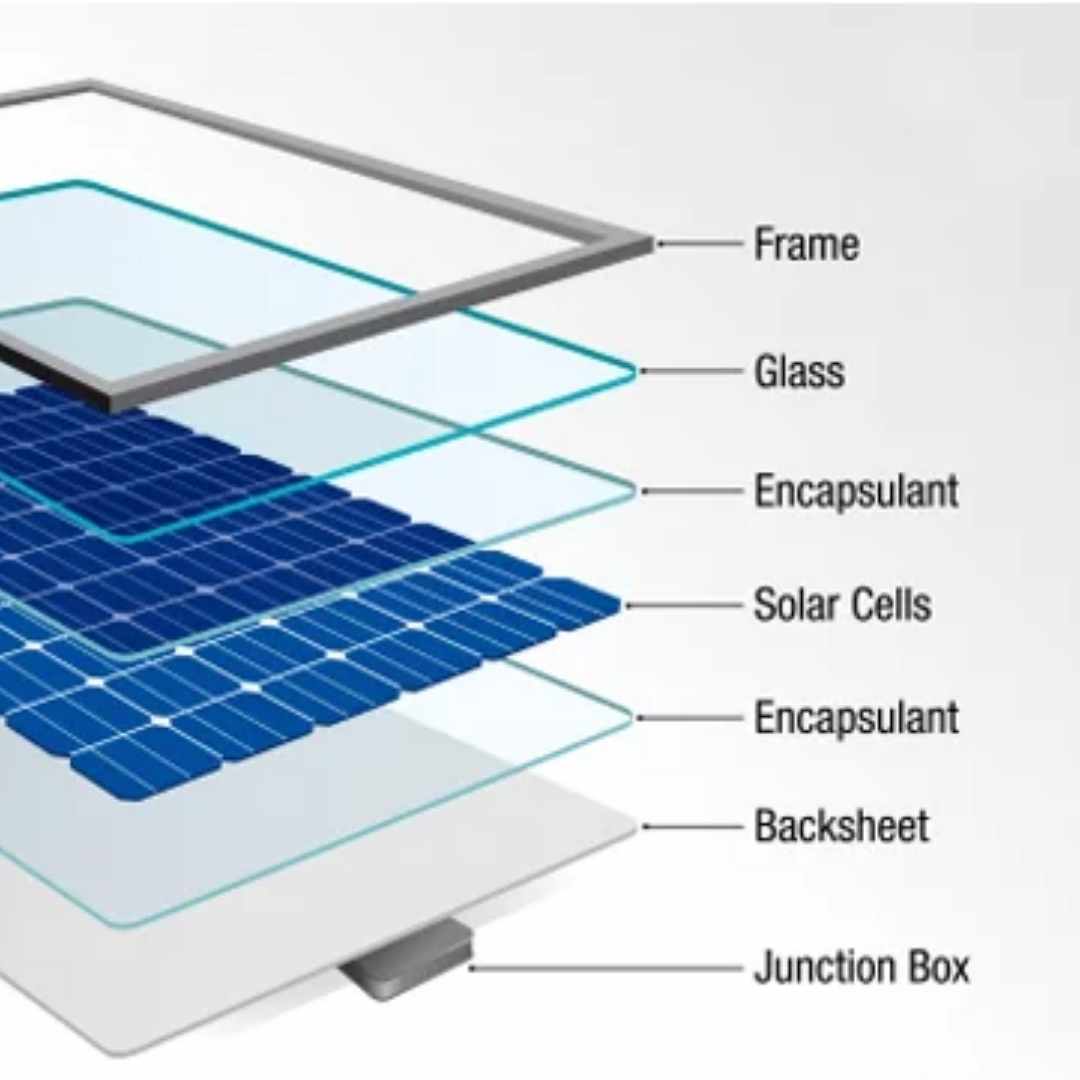
Cross-section geometry is where aluminum extrusion provides one of its greatest advantages.
Unlike a simple flat bar or fabricated plate, an extrusion can incorporate structural depth, ribs, channels, grooves, fastening interfaces and other functional features into one continuous section.
Depending on the application, designers may consider:
- Increased section depth
- Internal ribs
- Hollow chambers
- Flanges
- Fastening channels
- Clamp interfaces
- Cable-management channels
- Drainage features
- Reinforcement zones
- Integrated assembly interfaces
The objective is not maximum geometric complexity. Every additional feature can affect tooling, extrusion feasibility, material consumption and finishing.
The best cross-section is therefore the one that delivers the required structural and functional performance with a manufacturable geometry.
Design Insight: Increasing section depth or strategically positioning material can improve bending efficiency more effectively than simply increasing wall thickness throughout the entire profile.
Step 5: Select the Appropriate Wall Thickness
Wall thickness influences weight, stiffness, strength, extrusion feasibility and cost.
There is no universal wall thickness that is correct for every solar mounting extrusion. A thin wall may reduce material consumption but can create manufacturing, deformation or structural limitations. A substantially thicker wall can improve robustness while increasing weight and material cost.
| Design Approach | Potential Benefit | Potential Concern |
|---|---|---|
| Thin walls | Lower material usage | Extrusion feasibility and local deformation |
| Moderate walls | Balance of weight and performance | Requires application-specific optimization |
| Thick walls | Higher local robustness | Higher weight and material cost |
| Variable geometry | Material concentrated where needed | Greater tooling complexity |
Instead of selecting a wall thickness from a generic catalog recommendation, the designer should evaluate the complete cross-section and actual loading condition.
Step 6: Choose the Aluminum Alloy and Temper

Alloy selection should follow the mechanical and manufacturing requirements of the extrusion.
6063 aluminum is widely associated with extrusion-friendly geometries, surface quality and finishing performance. 6061 aluminum is often considered when higher structural performance and machining capability are important.
However, alloy selection should not be separated from profile geometry. Changing from one alloy to another does not automatically solve a poorly designed cross-section.
| Consideration | Design Question |
|---|---|
| Strength | What mechanical performance is required? |
| Extrudability | Can the geometry be produced efficiently? |
| Surface finish | Is appearance or anodizing performance important? |
| Machining | Will drilling, tapping or CNC operations be required? |
| Environment | What outdoor exposure will the component experience? |
| Cost | Does the alloy support the required TCO? |
For structural solar components, alloy and temper should be specified together with the cross-section and engineering load case.
Step 7: Design Connection and Fastening Features Into the Extrusion

One of the strongest reasons to use a custom extrusion is the ability to integrate connection features directly into the profile.
A solar mounting rail may incorporate channels for bolts, clamps or sliding fasteners. This can simplify installation and reduce the number of separate brackets or fabricated parts.
Potential integrated features include:
- T-slots
- Fastener channels
- Clamp interfaces
- Bracket connection zones
- Nut channels
- Mounting grooves
- Alignment features
However, the fastening system must be considered during extrusion design. Local wall thickness, access for fasteners and load transfer around connection points can materially affect the final component.
A profile that performs well under distributed loading may still require modification if concentrated clamp or bolt loads create local stresses.
Step 8: Consider Thermal Expansion in Solar Aluminum Profiles
Outdoor solar systems experience temperature changes throughout their operating life. Aluminum expands and contracts with temperature, making thermal movement an important consideration for long rails and large assemblies.
The extrusion design should therefore be coordinated with the mounting system’s expansion joints, fastener strategy and support arrangement.
For long solar installations, the engineer should consider:
- Profile length
- Expected temperature range
- Fixed and sliding connection points
- Expansion allowance
- Connection friction
- Interaction with adjacent materials
Thermal movement should be addressed at the system level rather than treated as an isolated material property.
Step 9: Design for Aluminum Extrusion Manufacturability
A technically effective profile must also be practical to extrude.
Complex geometry can increase die difficulty and manufacturing cost. Significant variations in wall thickness, extremely thin features and difficult hollow sections may require additional engineering review before production.
Manufacturability should be evaluated before finalizing the drawing.
| Profile Feature | Manufacturing Question |
|---|---|
| Thin walls | Can the required geometry be extruded consistently? |
| Deep channels | Will the die geometry remain stable? |
| Hollow sections | Is the required tooling practical? |
| Uneven wall thickness | Could it affect metal flow? |
| Sharp transitions | Can the profile be produced and finished reliably? |
| Integrated features | Do they reduce fabrication enough to justify tooling complexity? |
The best solar extrusion design balances structural efficiency with extrusion feasibility.
Step 10: Consider Tooling Cost and Production Volume

Custom aluminum extrusion requires tooling. The economics of that tooling depend heavily on profile complexity and production volume.
A custom profile may be justified when it provides measurable benefits such as lower material usage, fewer components, reduced machining or faster assembly.
For low-volume applications, a standard extrusion may sometimes be economically preferable. For high-volume OEM production, a custom profile can provide greater long-term value.
| Production Situation | Potentially Appropriate Strategy |
|---|---|
| Prototype or very low volume | Evaluate standard profiles first |
| Recurring moderate volume | Compare standard and custom TCO |
| High-volume production | Custom extrusion may justify tooling investment |
| Complex assembly | Integrated extrusion features may reduce downstream labor |
The correct decision should be based on total delivered component cost rather than tooling price alone.
Step 11: Define the Required Aluminum Extrusion Tolerances
Not every dimension on a solar profile drawing needs the same tolerance.
Critical interfaces may require tighter dimensional control than non-functional surfaces. Examples include clamp interfaces, module contact areas, connection channels and mating components.
Unnecessarily tight tolerances can increase manufacturing complexity and cost without improving the final system.
A practical drawing should therefore identify:
- Critical mating dimensions
- Functional dimensions
- Non-critical dimensions
- Cut-length requirements
- Surface requirements
- Applicable extrusion standards
For international B2B projects, tolerance requirements should be agreed before production rather than interpreted after the first shipment.
Step 12: Decide Whether Secondary Fabrication Is Required
Solar extrusions frequently require additional operations after extrusion.
These can include:
- Cutting to length
- Drilling
- Punching
- Tapping
- CNC machining
- Slotting
- Deburring
- Assembly
Secondary fabrication should be considered during the original profile design.
For example, an integrated fastening channel may eliminate a separate drilling operation. A dedicated locating feature may reduce assembly time. A modified extrusion geometry may eliminate a fabricated bracket.
These improvements can create a lower TCO even if the extrusion itself has a higher unit price.
Step 13: Select the Surface Finish for the Operating Environment
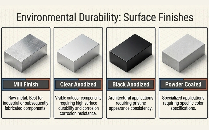
Solar mounting components are commonly exposed to sunlight, moisture, temperature changes and environmental contaminants. Surface treatment should therefore match the application and expected service environment.
| Finish | Potential Application | Primary Consideration |
|---|---|---|
| Mill finish | Industrial or subsequently fabricated components | Simple finishing requirements |
| Clear anodized | Visible outdoor solar components | Appearance and surface durability |
| Black anodized | Architectural solar components | Appearance and consistency |
| Powder coated | Specialized architectural applications | Color and coating specification |
For additional information about finished extrusion options, BOR-USA provides a dedicated anodized aluminum profile category.
Solar Extrusion Design Example: Mounting Rail
Consider a hypothetical aluminum mounting rail supporting photovoltaic modules between structural attachment points.
The initial design might specify only the rail’s outside dimensions. That approach is incomplete.
A better engineering workflow would define:
- Module weight and load distribution
- Wind and snow requirements
- Rail span
- Support spacing
- Fastener and clamp configuration
- Required stiffness and allowable deflection
- Alloy and temper
- Wall thickness
- Cross-section geometry
- Surface finish
- Cut length
- Required secondary fabrication
The resulting extrusion can then be evaluated for structural performance, manufacturability and total delivered cost.
This approach is more reliable than selecting a commercially available rail based only on dimensions or weight.
How to Reduce Weight Without Weakening a Solar Extrusion
Weight reduction is often an important objective in solar mounting systems, but the wrong approach can reduce structural performance.
Instead of removing material uniformly, designers can optimize where material is located within the cross-section.
Potential strategies include:
- Increasing section depth where bending resistance is needed
- Removing non-functional material
- Using internal ribs strategically
- Integrating fastening features
- Reducing unnecessary wall thickness
- Using hollow geometry where appropriate
- Eliminating separate brackets through profile integration
The objective is minimum functional mass, not simply minimum material weight.
Professional Recommendation: Optimize the cross-section before reducing material. A well-positioned rib or flange can sometimes provide greater structural value than additional aluminum distributed uniformly across the profile.
Custom vs. Standard Aluminum Profiles for Solar Mounting
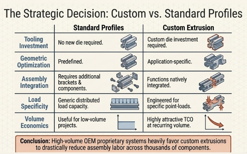
The decision between a standard and custom extrusion should be based on the application’s technical and economic requirements.
| Factor | Standard Profile | Custom Extrusion |
|---|---|---|
| Tooling | Usually no new die required | Custom die required |
| Geometry | Predefined | Application-specific |
| Integration | May require additional components | Functions can be integrated |
| Optimization | Limited to available sections | Can target specific load cases |
| Volume economics | Useful for lower-volume applications | Often more attractive at recurring volume |
| Assembly | May require additional brackets | Can reduce secondary components |
For proprietary solar mounting systems, a custom extrusion becomes particularly interesting when geometry can reduce assembly operations or improve material efficiency across thousands of components.
What Should an Engineer Include in a Solar Aluminum Extrusion Drawing?
A production-ready extrusion drawing should communicate the information necessary for both engineering review and manufacturing.
| Drawing Requirement | Purpose |
|---|---|
| Cross-section geometry | Defines the extrusion profile |
| Critical dimensions | Controls functional interfaces |
| Tolerances | Defines acceptable dimensional variation |
| Alloy and temper | Defines material condition |
| Surface finish | Defines appearance and treatment |
| Cut length | Defines finished component size |
| Fabrication requirements | Defines post-extrusion operations |
| Inspection requirements | Defines quality expectations |
A 2D section drawing can be sufficient for many extrusion quotations, while a 3D CAD model can provide additional information for complex assemblies and downstream fabrication.
Common Solar Aluminum Extrusion Design Mistakes
Designing by outside dimensions only
Outside dimensions do not define structural performance. Wall thickness, internal geometry, alloy, temper and loading direction must also be considered.
Reducing weight before evaluating stiffness
Material reduction without section analysis can increase deflection and create additional support requirements.
Ignoring connection loads
Clamps, bolts and brackets can introduce concentrated forces that differ significantly from distributed module loads.
Making every dimension extremely precise
Unnecessary precision can increase production cost without improving system performance.
Adding too many extrusion features
Integrated features are useful, but excessive complexity can increase die cost and manufacturing difficulty.
Ignoring downstream fabrication
A profile that looks inexpensive before machining may become expensive after cutting, drilling, tapping and assembly.
Designing without the annual production volume
Tooling economics and profile optimization can change substantially between prototype quantities and recurring high-volume production.
Solar Aluminum Extrusion Design Workflow
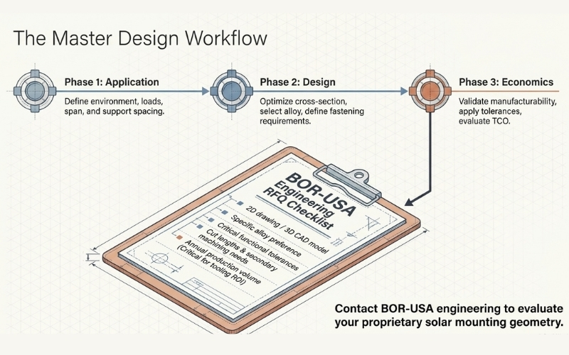
A practical development sequence can be summarized as follows:
- Define the solar application.
- Establish the operating environment.
- Determine wind, snow and other applicable loads.
- Define span and support spacing.
- Identify connection and fastening requirements.
- Develop the preliminary cross-section.
- Evaluate wall thickness and structural geometry.
- Select alloy and temper.
- Review extrusion manufacturability.
- Determine tolerances.
- Specify surface finish.
- Define cut length and fabrication requirements.
- Evaluate tooling and production economics.
- Validate samples against the approved drawing.
- Release the production specification.
This workflow helps connect engineering requirements with manufacturing realities before production begins.
How BOR-USA Supports Custom Solar Aluminum Extrusion Development
BOR-USA supports custom aluminum extrusion projects where profile geometry must be developed around a specific industrial or renewable energy application.
For solar mounting projects, the engineering discussion can include profile geometry, alloy selection, dimensional requirements, surface finish, cut length and secondary fabrication.
- Custom aluminum extrusion development
- Solar and renewable energy extrusion solutions
- Standard and custom profile options
- Multiple alloy and temper requirements
- Surface finishing options
- Cut-to-length services
- Secondary fabrication
- B2B and OEM production support
For projects requiring a custom profile, BOR-USA’s aluminum extrusion manufacturing services can be evaluated according to the required geometry, production volume and fabrication requirements.
What Information Should You Send to an Aluminum Extrusion Manufacturer?
To obtain a useful engineering and commercial quotation, provide as much of the following information as possible:
- 2D extrusion drawing
- 3D CAD model where available
- Alloy and temper preference
- Profile dimensions
- Critical tolerances
- Required cut length
- Surface finish
- Machining requirements
- Estimated initial quantity
- Annual production volume
- Application description
- Expected operating environment
For a proprietary solar mounting component, including annual volume is particularly important because the manufacturer can evaluate tooling investment and unit economics more accurately.
Final Engineering Takeaway
The best aluminum extrusion for a solar mounting system is not necessarily the lightest, thickest or strongest available profile. It is the profile that satisfies the application’s structural, dimensional, environmental and manufacturing requirements with the lowest practical total cost.
Successful solar extrusion design therefore connects five areas:
- Structural engineering — loads, span, stiffness and deflection
- Profile geometry — section depth, ribs, channels and material distribution
- Manufacturing — extrusion feasibility, tooling and tolerances
- Fabrication — cutting, drilling, machining and assembly
- Economics — material efficiency, tooling and long-term TCO
When these variables are evaluated together, a custom aluminum extrusion can do more than replace a standard profile. It can become an integrated component that reduces parts, simplifies assembly and improves production consistency.
BOR-USA Technical Note
When developing a solar mounting extrusion, start with the load case and connection requirements. Then optimize the cross-section, wall thickness and material distribution. After structural requirements are established, review extrusion manufacturability, tolerances, surface finish, fabrication and production volume.
This sequence helps prevent over-designed profiles, unnecessary material consumption and avoidable tooling or machining costs.
To discuss a custom solar extrusion project, contact BOR-USA with your available CAD drawing, profile dimensions, material requirements and expected production volume.
Frequently Asked Questions About Solar Aluminum Extrusion Design
How do you design an aluminum extrusion for a solar mounting system?
Start by defining the application, structural loads, unsupported span, connection geometry and allowable deflection. Then optimize the cross-section, wall thickness, alloy, tolerances and manufacturing requirements.
What is the most important factor in solar aluminum extrusion design?
The most important factor is application fit. Loads, span, profile geometry, connection design, alloy, tolerances and manufacturing requirements must be evaluated together.
How thick should a solar aluminum extrusion be?
There is no universal wall thickness. The required thickness depends on profile geometry, loading, span, alloy, extrusion feasibility and connection requirements.
Can a custom aluminum extrusion reduce solar mounting system costs?
Yes. A custom profile can reduce material usage, brackets, machining or assembly operations. The economic benefit should be evaluated using total delivered component cost rather than extrusion price alone.
Is 6063 or 6061 better for solar aluminum extrusions?
Neither alloy is universally better. 6063 is often selected for extrusion-friendly and appearance-sensitive applications, while 6061 is commonly considered where higher structural performance and machinability are important.
How does span affect solar mounting rail design?
Longer unsupported spans generally increase bending and deflection requirements. Section geometry, profile depth, support spacing and loading direction should therefore be evaluated together.
Can fastening channels be integrated into a solar aluminum profile?
Yes. Custom extrusion geometry can incorporate channels, grooves and fastening interfaces that may reduce separate brackets and simplify assembly.
Should solar aluminum profiles be anodized?
Anodizing can be appropriate for applications requiring a durable surface and consistent appearance. The correct finish depends on the environment, design requirements and project specification.
What drawings are needed for a custom solar aluminum extrusion?
A 2D section drawing is commonly used to define the extrusion geometry. A 3D CAD model can provide additional information for complex assemblies and secondary fabrication.
When is a custom extrusion better than a standard aluminum profile?
A custom extrusion can be advantageous when recurring production volume, proprietary geometry, material optimization or integrated assembly features justify the tooling investment.

Bor Aluminum – Content Producer